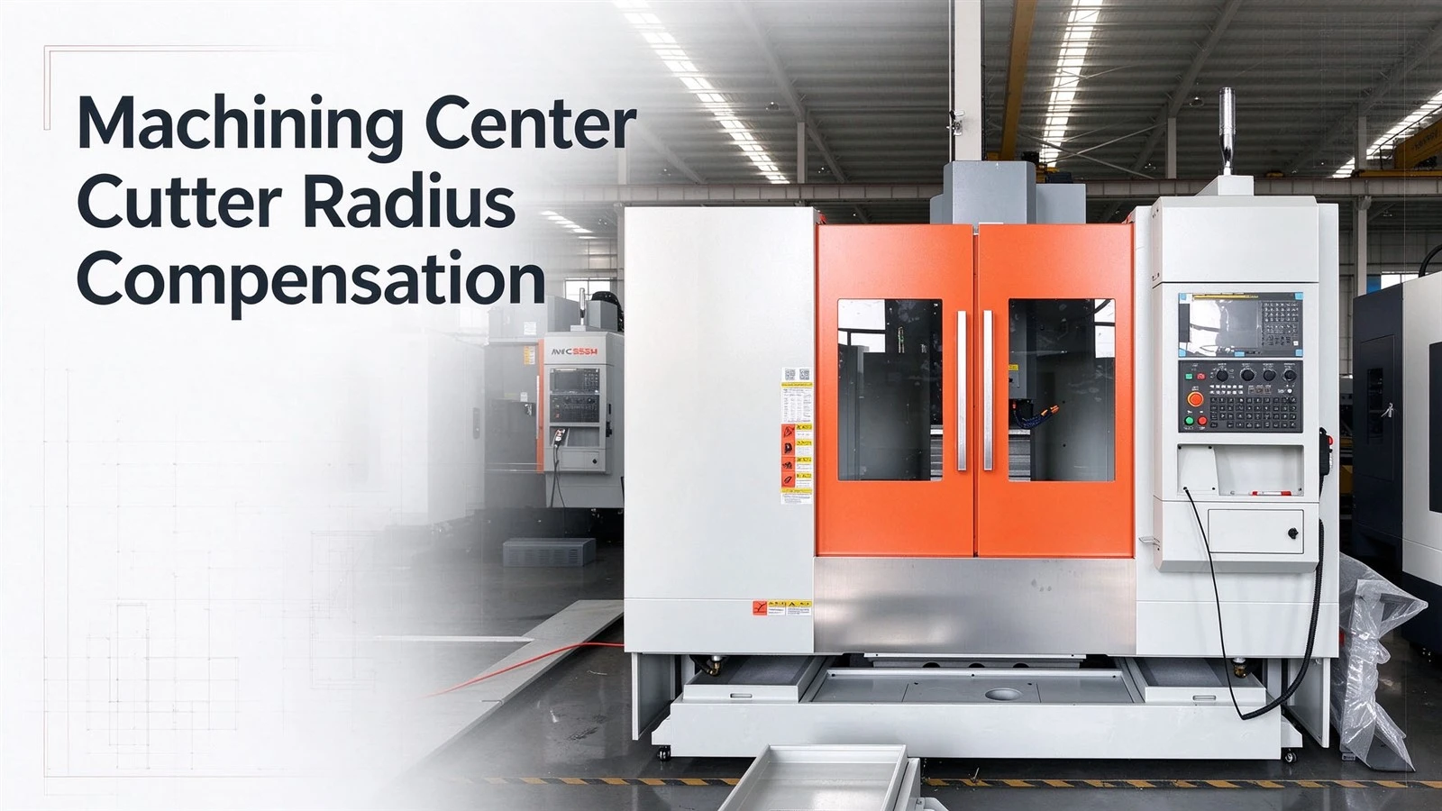
The concept of cutter radius compensation is analogous to that of tool length compensation: just as tool length compensation allows programmers to largely disregard the tool's actual length during programming, cutter radius compensation enables them to avoid worrying too much about the tool's diameter. While tool length compensation applies to all types of tools, cutter radius compensation is generally reserved for milling cutters. Cutter radius compensation is utilized when machining the external or internal contours of a workpiece, whereas only tool length compensation is required when facing a workpiece with an end mill. Because cutter radius compensation is a command that can be difficult to grasp and implement, many programmers are reluctant to use it. However, once understood and mastered, it offers significant convenience for both programming and machining operations.
When a programmer prepares to write a program for machining a workpiece's profile using a milling cutter, they must first perform detailed coordinate calculations based on the workpiece's dimensions and the tool's radius to determine the path the tool center will follow. The radius value used in these calculations corresponds specifically to the current milling cutter. If, after the arduous task of programming is complete, it is discovered that the cutter is unsuitable and a different diameter is required, the programmer must painstakingly recalculate the tool center path coordinates. While this may not be a major issue for simple workpieces, recalculating coordinates for complex mold profiles is extremely difficult.
Machining a workpiece profile typically involves both roughing and finishing stages. Once the roughing program is written and executed, the roughing phase is complete; however, because the workpiece dimensions have changed due to the roughing process, the tool center coordinates for the finishing pass must then be calculated, further increasing the workload. Cutter radius compensation resolves these complications effectively. Instead of factoring in the tool radius during initial programming, one can program based on the workpiece's nominal dimensions and simply store the tool radius value in the radius compensation register. Whether swapping milling cutters or transitioning between roughing and finishing, the workpiece dimensions can be controlled simply by adjusting the radius compensation value, requiring virtually no changes to the program itself.
Cutter Radius Compensation: Cutter radius compensation is implemented using the G41 and G42 commands. Compensation occurs in two directions-left or right-perpendicular to the direction of the tool's cutting feed, in accordance with the left-hand and right-hand rules: G41 represents left compensation (left-hand rule), and G42 represents right compensation (right-hand rule). When applying G41 or G42, special attention must be paid to the tool movement direction and coordinates that activate the compensation. The starting position for cutter radius compensation is critical; improper use can easily lead to errors in the tool's machining path.