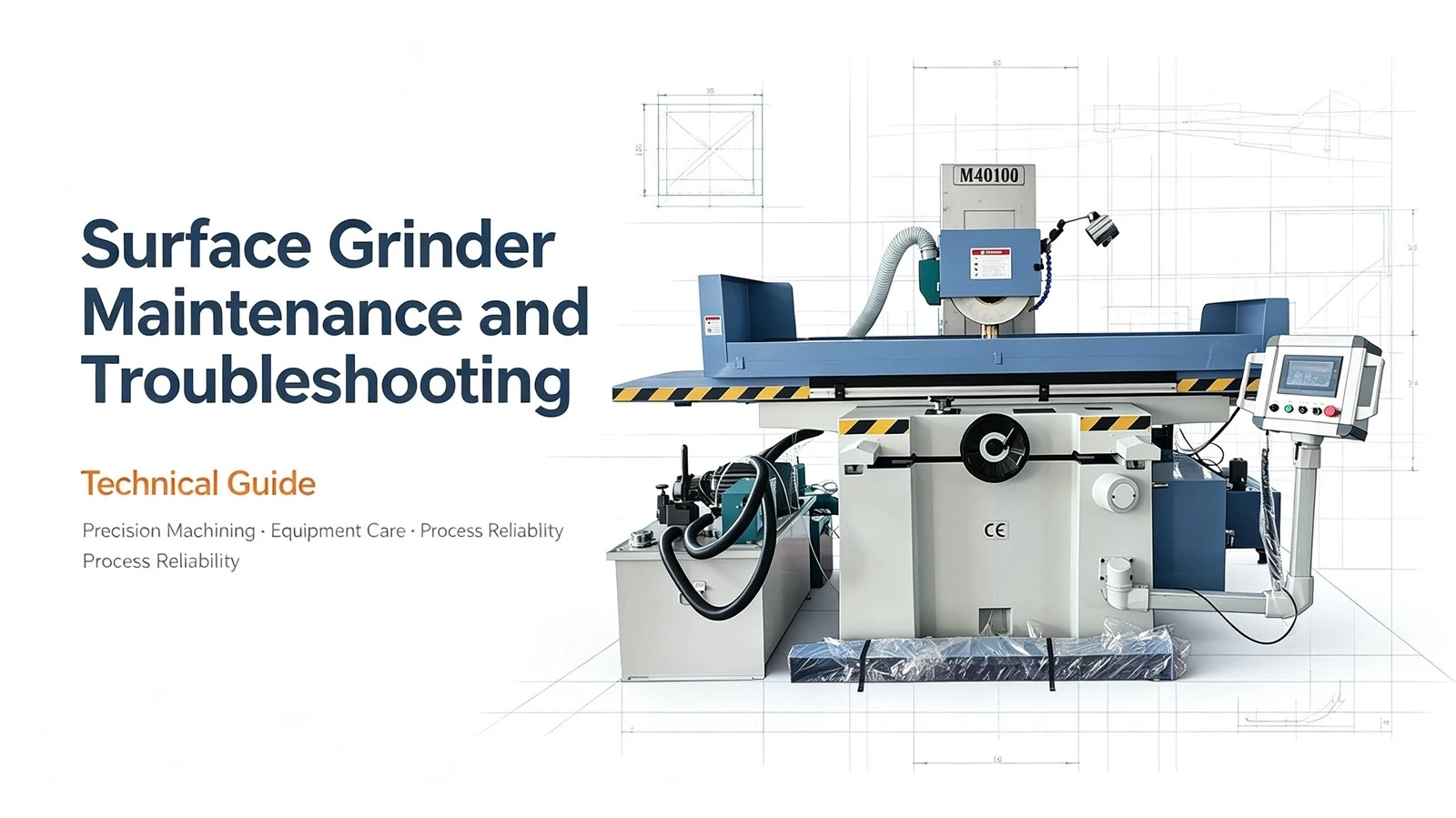
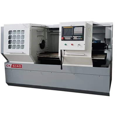
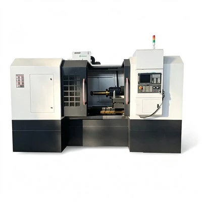
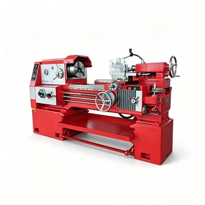
Surface grinders are a vital type of precision machine tool in the metalworking industry, widely used for processing molds, mechanical parts, and high-precision workpieces. Characterized by high machining precision, heavy-duty operation, and continuous running cycles, they demand rigorous standards for maintenance and troubleshooting. A scientific, systematic approach to maintenance and troubleshooting not only extends the machine's service life and boosts production efficiency but also ensures operational safety. This article provides a detailed overview of the entire maintenance and troubleshooting process for surface grinders, covering equipment structure, routine maintenance, fault types and analysis, troubleshooting steps, repair procedures, and management optimization.
I. Structure and Key Components of Surface Grinders
Surface grinders primarily consist of the following components:
Machine Bed and Worktable
The bed provides stable support for the machine and requires high rigidity and wear resistance.
The worktable handles workpiece clamping and motion transmission; its precision directly impacts machining quality.
Spindle System
Includes the spindle, motor, bearings, and grinding wheel mounting assembly.
Smooth spindle operation is crucial for ensuring machining precision and efficiency.
Grinding Wheel and Dressing Device
The grinding wheel performs the material removal (cutting) on the workpiece.
The dressing device ensures the wheel surface is flat and balanced, preventing machining errors.
Guideway and Leadscrew System
Guideways define the machine's motion paths, while leadscrews transmit feed motion.
The precision of guideways and leadscrews directly affects the positional accuracy between the worktable and the grinding wheel.
Hydraulic and Lubrication Systems
The hydraulic system facilitates workpiece clamping and the movement of auxiliary devices.
The lubrication system supplies lubricant to spindle bearings, guideways, and leadscrews to minimize friction and wear.
Electrical Control System
Controls machine movement, feed rates, grinding wheel speed, and the hydraulic system.
Includes switches, relays, and PLC or CNC systems.
Ⅱ. Daily maintenance methods
Check before starting up
- Check whether there is dust, debris or oil on the bed, workbench, guide rails and spindle.
- Check that the grinding wheel is firmly installed and the dressing device is in normal condition.
- Check the oil level of the lubrication system to ensure that the oil circuit is smooth.
- Check hydraulic system pressure and leakage.
- Confirm that the electrical system is normal and the limit switch and emergency stop button are available.
Inspection during operation
- Observe the smooth operation of the machine tool and check for abnormal vibration or noise.
- Check the wear of the grinding wheel to avoid affecting the machining accuracy.
- Monitor table movement and feed speed to ensure smooth operation.
- Check hydraulic pressure, lubricant supply and coolant flow.
- Cleaning and inspection after shutdown
- Clean the debris and dust on the surface of the guide rail, workbench and grinding wheel.
- Check the amount of oil in the lubrication system and the temperature of the bearings and screw.
- Perform a visual inspection of critical components such as cracks, wear or looseness.
Ⅲ. Common fault types and analysis
Spindle abnormality
- Symptoms: Ripples appear on the machined surface, vibration increases, or temperature rises.
- Cause: Bearing wear, insufficient lubrication, unbalanced grinding wheel or improper installation.
- Treatment: Replace the worn bearings, adjust the installation and balance of the grinding wheel, and ensure normal lubrication.
Workbench guide rails are worn or stuck
- Symptoms: The workbench movement is unstable and intermittent jamming occurs.
- Reason: Guide rail wear, dirt blockage or insufficient lubrication.
- Treatment: Clean the guide rail, add lubricating oil or replace the guide rail bushing.
Grinding wheel cracked or unevenly worn
- Symptoms: Processing marks or uneven cutting appear on the workpiece.
- Cause: Grinding wheel material mismatch, overload processing or improper dressing.
- Treatment: Replace the grinding wheel, trim the grinding wheel surface, and adjust the grinding parameters.
Hydraulic system failure
- Symptoms: The workpiece is not clamped firmly, the hydraulic action is slow or the pressure is abnormal.
- Cause: Insufficient hydraulic oil, blocked pipelines or damaged hydraulic components.
- Treatment: replenish hydraulic oil, clean pipelines, check valves and hydraulic pumps.
Electrical control abnormality
- Symptoms: The machine tool cannot be started, the control system alarms or the action fails.
- Reason: aging circuit, relay or switch failure, CNC system failure.
- Treatment: Check the electrical circuit, repair or replace damaged components, and eliminate the alarm fault.
IV. Troubleshooting Process
Initial Observation
Identify areas of abnormality-such as noise sources, points of vibration, or fluid leaks-by listening, looking, and touching.
Component-by-Component Inspection
Inspect specific systems sequentially: spindle, grinding wheel, guideways, worktable, hydraulic system, and electrical system.
Use manual operation or low-speed test runs to pinpoint the fault location.
Functional Testing
Test suspected components individually (e.g., rotating the grinding wheel, moving the worktable, or testing hydraulic clamping pressure).
Data Recording and Analysis
Record parameters such as bearing temperature, vibration levels, feed rate, and current; analyze the causes of any abnormalities.
V. Repair and Remediation Steps
Shutdown and Power Disconnection
Disconnect power and hydraulic supplies before maintenance to ensure safety.
Disassembly and Inspection
Remove worn or abnormal components (e.g., grinding wheel, bearings, lead screws, or hydraulic parts) according to the operation manual.
Inspect parts for wear, cracks, and thread damage.
Repair and Replacement
Replace severely worn or damaged grinding wheels, bearings, guideway bushings, or hydraulic components.
Refinish or realign parts with minor damage to ensure installation precision.
Reassembly and Commissioning
Ensure proper balance and clearances during installation; adjust grinding wheel balance and worktable movement.
Conduct a no-load test run to check for smooth machine movement and noise levels.
Conduct a loaded test run to observe machining results and precision.
Recording and Archiving
Document the fault cause, resolution method, parts replaced, and maintenance time.
Update equipment maintenance records to serve as a reference for future maintenance.
VI. Recommendations for Optimizing Equipment Management
Establish Comprehensive Record Management
Log usage time, maintenance, faults, and repair history for each surface grinder.
Analyze data to formulate scientific maintenance schedules and parts replacement cycles.
Conduct Regular Operator Training
Ensure familiarity with machine structure, daily maintenance, troubleshooting, and safety protocols.
Enhance operators' awareness of equipment management and their skill levels.
Implement Intelligent Monitoring
Install monitoring and alarm systems for temperature, vibration, and lubrication to enable real-time machine status monitoring.
Detect abnormalities early to reduce the risk of sudden breakdowns.
Periodic Maintenance and Optimization
A combination of routine care, weekly and monthly inspections, and annual overhauls ensures the long-term, stable operation of the machine tool.
Machining precision and efficiency are enhanced by optimizing grinding wheel materials, fixture designs, and machining parameters.
VII. Conclusion
The comprehensive system for surface grinder maintenance and troubleshooting encompasses routine maintenance, inspections, fault analysis, diagnostic methods, and repair procedures. Its core objectives are to ensure stable equipment operation, enhance machining precision, extend machine tool service life, reduce failure rates, and guarantee operational safety. Through scientific equipment management-integrating record-keeping, training, intelligent monitoring, and optimization strategies-long-term efficient, stable, and safe equipment operation can be achieved, providing a solid foundation for production efficiency and product quality.