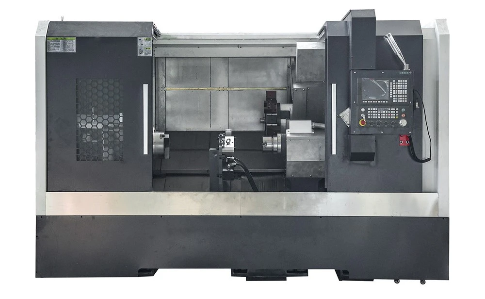
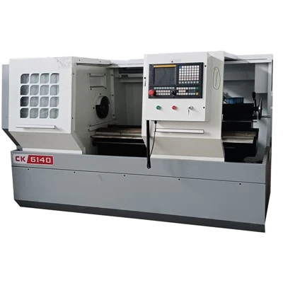
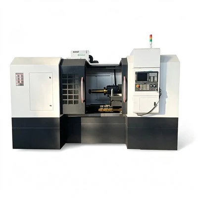
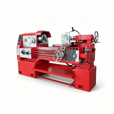
CNC slant-bed machine tools represent high-end equipment in modern machining, embodying the critical shift from traditional lathes toward high-precision, high-efficiency automated manufacturing. Compared to conventional flat-bed lathes, their defining characteristic is a bed guideway designed at an incline (typically 30° to 45°). This structural innovation alters the path of cutting force transmission and the method of chip evacuation, establishing the machine's dominance in precision turning operations.
The equipment's core advantages lie primarily in its rigid structure and optimized force distribution. The inclined bed design stabilizes the centers of gravity for components such as the headstock, turret, and tailstock; furthermore, cutting forces are transmitted more directly downward through the bed to the base, significantly reducing vibration and deformation during machining. This not only ensures high part precision and superior surface finish but also extends tool life and boosts cutting efficiency, making the machine particularly well-suited for both heavy-duty and precision cutting tasks. Another major highlight is its excellent chip evacuation performance. Thanks to the inclined guideway layout, chips slide away naturally under gravity, preventing the wear and jamming issues caused by chip accumulation on guideways or ball screws; this effectively extends the equipment's service life and reduces maintenance frequency.
Operating procedures for CNC slant-bed machine tools:
I. Pre-start inspection (First step before commencing work)
Wear close-fitting work clothes, non-slip safety shoes, and protective eyewear; the wearing of gloves, scarves, or loose accessories is strictly prohibited, and long hair must be tucked inside a work cap.
Clear away metal chips and debris from the area surrounding the machine, the slant-bed guideways, the chuck, and the turret surface; verify that the fully enclosed safety guard is intact and the door interlock is functional, and ensure the emergency stop button is reset (popped out).Ensure the lubricating oil level is within the standard range; check that lubrication lines are free of leaks and air bubbles.
Ensure the coolant tank level is sufficient; check that the cutting fluid has not deteriorated or developed an odor and that the filter screen is not clogged.
Verify the hydraulic station pressure is within the standard 6–8 MPa range; ensure there are no oil leaks and the oil temperature is normal.
After a prolonged shutdown, manually lubricate the guideways and ball screws.
Ensure the power supply voltage is stable and cables are undamaged; for pneumatic models, maintain air pressure between 0.5 and 0.7 MPa; check that there are no fault alarms for the chip conveyor, oil mist lubricator, etc.
Inspect chuck jaws, tailstock centers, and steady rests for cracks or wear; check inserts for chipping or damage-do not install substandard tools.
II. Power-up, Homing, and Machine Warm-up
Switch on the main power → turn on the electrical cabinet switch → activate the control panel power; wait for the CNC system to complete its self-test and clear any alarm codes.
Start the hydraulic pump and verify stable oil pressure; start the automatic lubrication pump to supply oil to the guideways and ball screws.
Return the machine to the reference point (homing-a mandatory step).
Switch to Manual (JOG) mode and execute the origin return for the X and Z axes; return the Z-axis first, followed by the X-axis, to establish the mechanical datum coordinates and prevent tool collisions or dimensional drift.
Spindle warm-up: Run the spindle at a low speed (300–500 rpm) without a load for 3–5 minutes, then increase the speed to half of the machining speed and run for 20 minutes to eliminate spindle bearing clearance and ensure stable machining accuracy.
III. Workpiece and Tool Clamping Operations
(1) Workpiece Clamping (Hydraulic Hollow Chuck)
Clean metal chips and burrs from the inner surfaces of the chuck jaws to prevent tilted clamping;
Insert the workpiece and step on the foot pedal to clamp it; ensure a clamping length of ≥5mm; use a copper shim for thin-walled parts to prevent clamping damage;
Manually rotate the workpiece slightly to ensure it is secure; for slender shafts, use the hydraulic tailstock center for auxiliary support and lock the tailstock quill;
Close the machine guard door to activate the safety interlock; opening the door will automatically cut off the feed and spindle rotation.
(2) Turret Tool Installation
Switch to manual mode, stop the spindle, and index the turret to an empty station;
Wipe chips from the tool holder mounting surfaces; install external turning tools, internal boring tools, and parting tools; align tool tips with the spindle center (tolerance ±0.02mm);
Tighten turret mounting bolts in a crisscross pattern to prevent tool deflection during heavy cutting; limit the overhang of internal boring tools to avoid collisions with the turret during rotation;
After installing all tools, manually index through all stations to check for interference or contact with the machine bed or tailstock.
IV. Tool Setting and Compensation (Critical Precision Steps)
Use the trial-cut method to establish the workpiece coordinate system:
X-axis Tool Setting
Rotate the spindle, move the tool at low speed to lightly turn the workpiece's outer diameter, retract the tool in the Z-direction while keeping the X-axis stationary; stop the spindle, measure the outer diameter with calipers, and input the value into the X-axis geometry offset for the corresponding tool number.
Z-axis Tool Setting
Gently touch the tool against the workpiece end face, retract the tool in the X-direction, and input the Z-coordinate into the tool's Z-axis geometry offset.
Multi-tool Setting
Sequentially switch to all machining tools (e.g., No. 1, No. 2, No. 3...), repeat the trial cut, and input the tool offsets.
Wear Compensation Allowance
Reserve a small X/Z wear adjustment value for finishing; subsequent dimensional deviations can be corrected by directly modifying the wear offset without re-setting the tool.
After tool setting is complete, manually move the axes slowly across the full X/Z travel range to simulate the tool path and verify there are no collisions with the chuck, tailstock, turret, or guideways.
V. Program Input, Simulation, and Dry Run Verification
Program Input
Import via USB, manual MDI editing, or DNC online transfer of G/M machining programs; verify coordinates, spindle speed (S), feed rate (F), cycle commands, signs (+/-), and decimal points line by line to eliminate syntax errors.
Graphic Simulation
Enable the system's graphic simulation to view the tool path in full-screen mode and check for risks of over-travel, collisions, or over-cutting.
Machine Lock / Dry Run (Mandatory for new programs)
Activate the machine lock and dry run switches to quickly execute the complete program and verify the logic; dry run verifies the code only-axes do not move, and no cutting occurs.
Preparation for Debugging Run with Overrides
Deactivate machine lock; set feed rate override to 20%–30% and spindle speed override to 50%; stand by in single-block mode.
VI. Single-block trial cutting, dimensional adjustment, and automatic batch processing
Single-block trial cutting (mandatory for the first piece)
Turn on the coolant and aim the nozzle at the cutting zone; start single-block operation. Observe the cutting sound, chip evacuation, and vibration after executing each block; proceed to the next block only if there are no abnormalities.
Dimensional inspection of the first piece
After machining the first piece, stop the spindle, open the door, and remove the workpiece; measure the outer diameter, length, and inner bore using calipers and micrometers.
Fine-tuning wear compensation
If the dimension is oversized, decrease the X-axis wear offset; if undersized, increase the X-axis wear offset. Adjust the Z-axis wear offset for length deviations. Repeat trial cutting until dimensions meet specifications.
Automatic batch processing
Once dimensions are stable, switch to continuous cycle mode, restore feed and spindle overrides to 100%, and proceed with automatic batch production.
Key inspection points during machining
Check every 10 minutes: oil pressure, lubrication, coolant flow, chip evacuation (sliding down the slant bed), tool wear, and for any abnormal noise or vibration. Immediately pause the machine if harsh noise, smoke, or severe vibration occurs.
VII. Protocols for temporary shutdowns
Normal temporary shutdown (for part replacement or measurement)
Press [Cycle Stop] → stop spindle → turn off coolant pump → wait for the workpiece to come to a complete stop before opening the door. Reaching in to measure while the spindle is rotating is strictly prohibited.
Emergency shutdown due to malfunction
In the event of tool collision, abnormal noise, smoke, loose workpiece, or oil/coolant leakage, immediately press the red emergency stop button. Cut off power to troubleshoot; after resetting, the machine must return to the reference point (home) and tool offsets must be verified before resuming machining.
Leaving the workstation
Pause the program, stop the spindle, and close the safety door securely. Leaving the equipment running automatically without supervision is prohibited.
VIII. Shutdown, Cleanup, and Routine Maintenance
Post-Machining Procedure
Upon completion of all machining operations, manually move the turret to a safe position in the center of the machine, ensuring the X and Z axes are clear of their travel limits; retract the tailstock quill.
Shutdown Sequence
Turn off the coolant pump → Stop the lubrication and hydraulic pumps → Shut down the CNC system → Cut power to the electrical cabinet → Disconnect the main power supply.